
Rarefied clearance gas flows in vacuum pumps with moving boundaries in any direction
Content
Project description - Contact person - Cooperation / Funding
Project description
Investigation of clearance flows, with the aim of a better accuracy of the simulation of vacuum pumps
Nowadays the application of vacuum technology is indispensable in many fields of research and technology. It is used for the fabrication of microelectronic components, for packaging food, for degassing liquids and for metal casting, to name just a few applications. Applications of vacuum technology can also be found in scientific fields such as particle physics, materials science, plasma research etc.
The application of vacuum technology covers a pressures range of about 15 decades from 10-10 Pa to 105 Pa, i.e. an investigation of all types of gas flows from free molecular flow to continuous flow is necessary. The dimensioning and designing of vacuum pumps is a particular challenge for these pressure ranges.
With vacuum pumps of today, it has become a routine to produce vacuum and to keep it stable under various circumstances. Still, there is the potential to optimize vacuum pumps, which come in various designs. Considering steadily rising energy prices, this potential should be used.
The performance characteristic of positive displacement vacuum pumps, is primarily determined by the size and geometry of the machines clearances e.g. between rotor and housing. The design of the clearance and the control of the clearance flow in various different pressure ranges from ultrahigh vacuum to continuous ranges are crucial to purposefully design and optimize a vacuum pump. Therefore not only the mass flow rate but also the heat transfer is of interest.
The modeling of the flow in vacuum pumps is characterized by the following listed properties with respect to the Knudsen number which defines the ratio of the molecular mean free path to a characteristic length of a geometry:
- The flow has to be modeled for a large pressure range, which covers continuous flows as well as molecular flows. While the Navier–Stokes equations apply for continuous flows (Kn < 0,01), they are not valid for rarefied gas flows.
- If the Knudsen number lies between 0.01 and 0.1, one speaks of the slip region of the flow and a velocity slip and a temperature jump occurs in normal direction of the walls.
- For Knudsen numbers 0.1 < Kn < 10 the number of intermolecular collisions and wall interactions are almost the same. In this so called transition regime the flow has to be calculated by means of the boltzmann equation.
- For Knudsen numbers Kn > 10 the intermolecular collisions occur rarely thus they can be neglected. Thus a free molecular flow can be modeled.
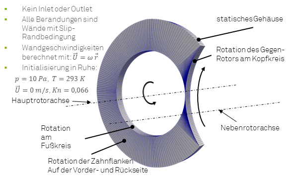
- The influence of a moving boundary in the range of rarefied flows is significant and cannot be neglected in the modeling process, because every molecule interacting with the moving wall gets a more probable orientation in the direction of the moving wall.
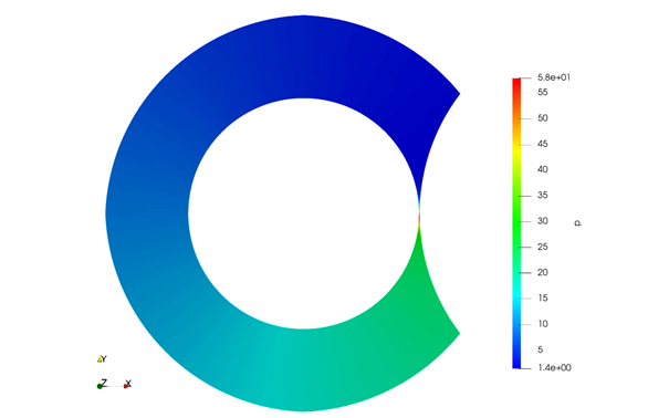
As part of this project the clearance flow in dry-running vacuum pumps is beeing investigated by means of simulations and experiments. The focus lies on the boundaries of the clearances between two vacuum chambers, which are influenced by the movement of the walls in and transversely to the flow direction. It can be shown, that the vacuum chamber does not have homogenious states because of the rotation, but there occurs a pressure gradient along the chamber due to the superposition of Couette and Poiseuille flow. This causes a non homogenious inlet and outlet pressure along the width of the housing clearance and pressure boundaries for the intermesh clearances which differ highly from the mean chamber pressure.
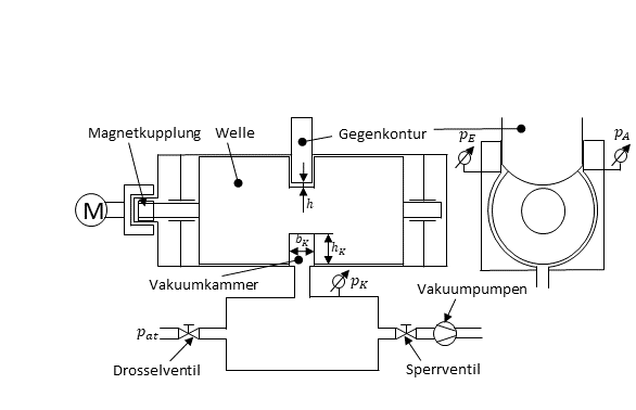
Based on this, a test rig for measuring the pressure gradient within a working chamber is developed, via which the boundary conditions of the adjacent clearances can be determined. The sketch shown in Figure 3 shows the basic structure. Here, the vacuum chamber is in the gap space between a rotatably mounted shaft and the enclosing housing. By the production of different disks, the ratio of chamber height to chamber width should be varied. With a counter contour in the form of the crown circle of a counter rotor, the working chamber is interrupted, so analogous to the machine there exist intermesh clerarances. To determine the pressure profile, the static pressure is measured via absolute pressure sensors on both sides of the counter contour. A third pressure measuring point is located in the recipient on the opposite side of the counter contour. This is connected via a check valve with vacuum pumps and has a connection to the atmosphere via a throttle valve, so that the average pressure in the working chamber can be adjusted via the control of the valves. In order to minimize the leakage within the experimental setup, all connections to the atmosphere are sealed with O-rings. For this purpose, a magnetic clutch is used, which allows a sealing of the drive train.
Beside the experimental setup and the and the comparison with the simulation results using the CFD, a one-dimensional theory to calculate rarefied gas flows is adapted from the literature and extended to apply to the working chamber. First calculations show a good qualitative match in comparison with CFD. A comparison with measurents is still pending.
Contact person
Cooperation / Funding
This project is funded by the Federal Ministry for Economic Affairs and Energy (BMWi) (IGF No.: 19859 N/1) and Forschungskuratorium Maschinenbau (FKM)