Steam test rig
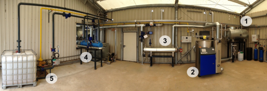
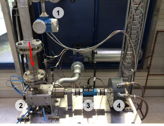
The steam test rig at the Chair of Fluidics at TU Dortmund University is used for the investigation and testing of expansion devices in a Rankine-cycle. The components for steam generation and condensation, figure 1, and a test bench for expansion devices, figure 2, serve as the test rig's mayor units. The working principle corresponds to a simple Rankine-cycle. Water is thermally and chemically conditioned in a feed water module and afterwards conveyed to a gas-fired boiler by a feed pump, where it is evaporated. An additional superheating of the saturated steam in an electric superheater is optional. The pressurised steam is then fed to the expander mounted on the test bench after passing several control valves. The expander mass flow rate and inlet pressure are controlled through modulation of a bypass valve. The depressurised steam is condensed in a straight-tube heat exchanger and led to a reservoir, from where it is finally fed back to the feed water module. The heat of condensation is transferred to a cooling circuit and released to the ambient through radiators. The expander test bench is equipped with extensive measurement equipment to examine the expander's operational behaviour. System control of the test rig, data logging and processing is performed from an external control room.
- Steam Generation
Thermal power of the test rig amounts to approx. 330 kW (300 kW gas-powered, 30 kW electric superheating). Saturated or superheated steam (maximal superheating 50 K) can be generated with a pressure of up to 10 bar. The maximal mass flow rate is approximately 0.1 kg/s.
- Measurement equipment
The steam cycle is equiped with several measurement points for the determination of pressure and temperature. Temperature measurement is performed with thermocouples whereas system pressure is measured with piezoresistive pressure sensors. The steam flow is metered with a coriolis flow meter immediately before entering the expander. Additionally, a magnetic inductive flow meter is used to measure the condensate flow. The obtained torque from the expander and expander speed are recorded with a torque sensor. All data is logged, processed and stored in a centralised measurement system.
- Control systems
Several control systems are used to hold constant system and expander operation points. Motor operated valves in the piping and the boiler control system provide constant inlet pressure for the expansion device. A constant inlet temperature is realised through controlling of the electric superheater. The rotational speed of the expander is held constant with a controlled eddy current brake.
- Currently there are no elements available.
Support
Federal Ministry for Economic Affairs and Energy


